
Recently in my Software Construction, Design and Architecture class, we have been getting into UML class diagrams. The class diagrams provide an understandable system structure and the relationships among the objects. Each relationship has a distinct visual representation based on arrows:

In this case, we started using Visual Studio Code and PlantUML to model class diagrams. I referred to the UML documentation that was provided to get a better understanding of how to display each type of arrow in PlantUML.
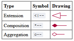
As shown above, there are three kinds of relationships that can be represented in PlantUML: Extension, Composition, and Aggregation. I am not totally familiar with the use of composition and aggregation as we’ve only been focusing on models that use extends and implements in class. I wanted to get a better understanding on how to read UML class diagrams and to be able to tell the relationships between the objects on the diagram.
With PlantUML and Markdown preview in Visual Studio Code, you can see changes to the UML diagram in real time as you modify the code. What you write in the code will reflect what shows on the diagram. You can also manually draw the relationship, which provides more customization such as arrow length, direction, etc. In addition to solid lines, you can use dotted lines to represent dependencies.
Extends is represented on a UML diagram as a solid line with an empty arrow. By writing that Class A extends Class B, you will see the diagram update show a line with an empty arrow point from Class A to Class B. Instead, you can also write Class A <|– Class B in order to display it on the diagram. When viewing the diagram alone, you can assume that Class A has access to all attributes and operations available in Class B.
Implements is represented on a UML diagram as a variation of the extension arrow, with a dotted line instead. By writing that Class A implements Interface, the diagram will be updated to show a dotted line with an empty arrow pointing from Class A to Interface. To draw an inheritance arrow on the diagram, you can write Class A <|.. Interface. When taking a look at the diagram, you can assume that Class A has access to the operations of Interface and contains the code for them.
I found the PlantUML documentation very useful as it contains basically everything you need to know about using PlantUML to create class diagrams. I also really enjoyed the functionality to modify the example diagrams to experiment with the features that you just read up on. Overall, I think that UML class diagrams are a good way to visualize a class structure. The arrows are easy to follow and help in understanding the relationship between classes.
From the blog CS@Worcester – Null Pointer by vrotimmy and used with permission of the author. All other rights reserved by the author.